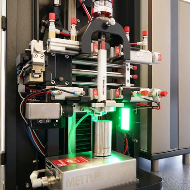
Pipettes and infusion sets are produced in the millions via plastic injection molding. Product cycles are getting shorter, and geometric complexity is increasing. At the same time, regulations require extensive validation, complete documentation, and traceability. Computer tomography-based measuring devices, such as the Tomo Scope XS series from Werth Messtechnik, demonstrate how validation times and staffing requirements can be reduced.
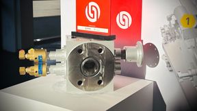
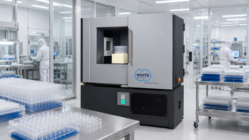
In-Process CT Measurement: The Tomo Scope XS Plus inspects pipette tips using an integrated workpiece changer directly in the production environment.
(Bild: Werth Measurement Technology)
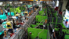
Manufacturers of injection-molded parts for the medical technology industry face a conflict of objectives. On the one hand, more and more new, increasingly complex products are entering the market in ever-shorter cycles. On the other hand, the European Medical Device Regulation (MDR) (EU 2017/745) requires extensive validation steps, complete documentation, and traceability. For the U.S. market, the FDA quality regulation 21 CFR Part 820 applies: Since February 2026, it has been known as the Quality Management System Regulation (QMSR) and refers directly to ISO 13485. More features on more parts must be tested in less time. Any delay postpones market entry.
It is tested rather than measured
The situation is exacerbated by the high proportion of manual inspections. “Gauges, visual inspections for burrs, or functional tests are attribute inspections: They provide only a pass/fail result (OK/NOK), depend on the operator, and do not provide any insight into the manufacturing process,” explains Dipl.-Ing. (FH) Tristan Schubert, Head of Technical Sales at Werth Messtechnik, a manufacturer of multisensor and computed tomography coordinate measuring machines for industrial quality assurance. Schubert adds: “We’re teaching instead of measuring. Why and at what point a mold starts producing defective parts remains unclear. As the number of cavities increases, the effort required grows exponentially: Where four workpieces used to be inspected per shot, today there are often 64 or 128.”
Measure with CT, not just inspect
According to Schubert, computed tomography (CT) is often used in the market purely as an inspection solution—for example, to detect voids, burrs, or missing components in an assembly. This falls short when it comes to process monitoring: Only quantitative measurements reveal trends before workpieces fall outside the tolerance range.
The difference lies in the design of the device. In 2005, for example, Werth Messtechnik introduced the Tomo Scope, the world’s first coordinate measuring machine with computed tomography, developed specifically for dimensional metrology. A coordinate measuring machine with computed tomography features high-precision axes and a calibrated coordinate system: All axis errors are calibrated, known, and corrected. The scale of the reconstructed volume is therefore fixed without the need for subsequent scaling; the reconstruction is completed immediately after the last projection, and the measurement is traceable.
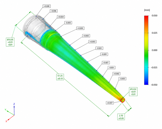
Measurement and inspection in a single measurement process: Dimensions, tolerances, and surface deviations of a pipette tip in a single evaluation.
(Bild: Werth Measurement Technology)
In contrast, inspection CTs determine the acquisition geometry retrospectively from the image stack and require an additional post-processing step. “In addition, the scale must often first be determined by measuring calibrated scales, such as ball-on-ball scales with two balls whose diameters and spacing are known: Only with this scaling does the reconstructed volume acquire its dimensional representation,” says Schubert. Traceable measurement is therefore not readily possible. Schubert adds: “In short: A measurement CT can always also inspect, but an inspection CT cannot necessarily measure.”
According to Schubert, in practice, CT coordinate measuring machines allow inspection and measurement to be combined into a single measurement process: A burr is not only detected, but its height is also measured—for example, as an early indicator of tool wear. Similarly, a completeness check of an assembly can be combined with dimensional analysis.
Closed-loop measurement system for MDR and FDA
In addition to accurate measurements, MDR and QMSR require, above all, traceability: Who measured what, when, using what, and with what result? “In the CT environment, multiple software solutions are often integrated for this purpose,” says Schubert. “Machine control, image acquisition, reconstruction, and evaluation come from different sources. Every interface is a potential break in the documentation chain and a possible gateway for operator influence on the result.”
With Werth Tomo Scope devices, a single software package—Winwerth—handles the entire process, from device control and reconstruction to evaluation and reporting. This closed measurement chain ensures that the operator has no influence on the measurement result: Regardless of who loads the workpiece and starts the measurement, the same result is obtained. A complete measurement history is available for audits. In addition, Werth offers CT coordinate measuring machines calibrated in accordance with the specifications of the German Accreditation Body (DAkkS): DAkkS calibration has been mandatory in the automotive industry for several years, and it is increasingly required in the medical technology sector.
Date: 08.12.2025
Naturally, we always handle your personal data responsibly. Any personal data we receive from you is processed in accordance with applicable data protection legislation. For detailed information please see our privacy policy.
Consent to the use of data for promotional purposes
I hereby consent to Vogel Communications Group GmbH & Co. KG, Max-Planck-Str. 7-9, 97082 Würzburg including any affiliated companies according to §§ 15 et seq. AktG (hereafter: Vogel Communications Group) using my e-mail address to send editorial newsletters. A list of all affiliated companies can be found here
Newsletter content may include all products and services of any companies mentioned above, including for example specialist journals and books, events and fairs as well as event-related products and services, print and digital media offers and services such as additional (editorial) newsletters, raffles, lead campaigns, market research both online and offline, specialist webportals and e-learning offers. In case my personal telephone number has also been collected, it may be used for offers of aforementioned products, for services of the companies mentioned above, and market research purposes.
Additionally, my consent also includes the processing of my email address and telephone number for data matching for marketing purposes with select advertising partners such as LinkedIn, Google, and Meta. For this, Vogel Communications Group may transmit said data in hashed form to the advertising partners who then use said data to determine whether I am also a member of the mentioned advertising partner portals. Vogel Communications Group uses this feature for the purposes of re-targeting (up-selling, cross-selling, and customer loyalty), generating so-called look-alike audiences for acquisition of new customers, and as basis for exclusion for on-going advertising campaigns. Further information can be found in section “data matching for marketing purposes”.
In case I access protected data on Internet portals of Vogel Communications Group including any affiliated companies according to §§ 15 et seq. AktG, I need to provide further data in order to register for the access to such content. In return for this free access to editorial content, my data may be used in accordance with this consent for the purposes stated here. This does not apply to data matching for marketing purposes.
Right of revocation
I understand that I can revoke my consent at will. My revocation does not change the lawfulness of data processing that was conducted based on my consent leading up to my revocation. One option to declare my revocation is to use the contact form found at https://contact.vogel.de. In case I no longer wish to receive certain newsletters, I have subscribed to, I can also click on the unsubscribe link included at the end of a newsletter. Further information regarding my right of revocation and the implementation of it as well as the consequences of my revocation can be found in the data protection declaration, section editorial newsletter.
According to Schubert, the extent to which measurement technology contributes to cost-effectiveness is evident in three areas: usable manufacturing tolerance, equipment availability, and labor costs.
High measurement accuracy increases the usable tolerance
“The accuracy of the measuring instrument determines the usable manufacturing tolerance,” Schubert emphasizes. According to the decision rules in ISO 14253-1, the measurement uncertainty must be taken into account at both limits of the tolerance band when verifying conformity. Schubert: “Only workpieces whose measured value lies within the tolerance by more than the measurement uncertainty are reliably considered compliant. The greater the measurement uncertainty, the narrower the usable manufacturing tolerance, and the more workpieces that are borderline must be discarded as a precaution.”
As a rule of thumb, according to Schubert, the measurement uncertainty should be 10 times smaller than the tolerance: This ensures that the tolerance band is available to the manufacturing machines and is not consumed by the measurement technology. According to their specifications, the Tomo Scope XS systems are among the most accurate CT coordinate measuring machines on the market. A more accurate measuring system increases the usable tolerance and reduces scrap and inspection costs, even if it is more expensive to purchase.
High measurement speed increases equipment availability
In production-accompanying applications, equipment availability is closely linked to measurement speed. For injection-molded parts used in medical technology, structural resolutions of 20 µm to 30 µm and finer are required. The Werth X-ray sources (130 kV to 230 kV) with transmission targets used in the Tomo Scope XS series enable measurements up to five times faster than conventional reflection sources at the same resolution within this resolution range.
"If production approval depends on the measuring device, any tube maintenance would, in the worst case, mean a production shutdown," said Schubert. The maintenance cycle for the X-ray sources used by Werth is twelve months and coincides with regular equipment maintenance—a standard interval for coordinate measuring machines. There is no need for manual filament replacement. Thanks to the modular design, the X-ray source, detector, and their spacing can be adapted to the measurement task. The Werth Clear CT reconstruction method with a helical trajectory inherently eliminates conical beam artifacts. Because this also allows for the use of large cone angles, the workpiece can be positioned close to the X-ray source: According to the inverse square law, the usable radiation intensity increases, measurement times are reduced, and the devices can be built significantly more compactly.
Automation in three phases reduces staffing costs
Automation begins with labor costs. In medical injection molding, production often runs around the clock; three levels of automation have become standard to ensure the necessary flow of parts. Schubert explains: “The first level is manual loading by the operator. The second stage is an integrated workpiece changer: Multiple workpieces are stored in the machine and automatically positioned within the radiation shielding enclosure using the machine’s own axes.” This eliminates the need for additional safety circuits or protective fences. This allows for the unmanned measurement of identical or different workpieces, for example during the night shift.
“For higher production volumes, the third stage involves external feeding via a robot or conveyor system; two machine openings allow for automated loading from the rear while manual operation can continue at the front,” Schubert continues. At Werth Messtechnik, turnkey solutions are also implemented by a dedicated department for special projects.
Real-World Examples: Pipette Tips and Insulin Pens
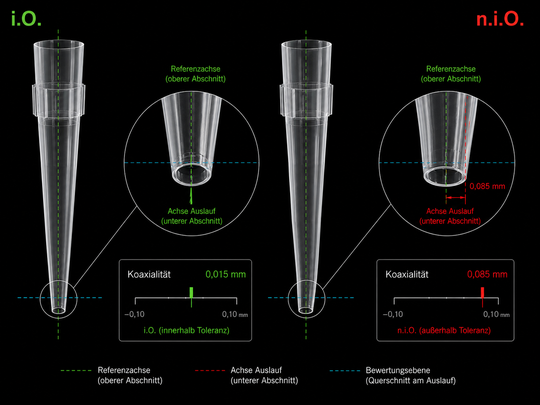
Coaxiality of the inlet and outlet as a test criterion: The measured value distinguishes between workpieces that are within and outside the tolerance.
(Bild: Werth Measurement Technology)
Schubert reports that the way all three factors interact became particularly evident during the COVID-19 pandemic: “Demand for pipette tips for automated testing machines skyrocketed, and with it, the number of cavities in the molds increased. Manual inspection for flash and completeness, as well as measuring the coaxiality of the inlet and outlet and the diameters—which ensure proper flow—were no longer feasible given these production volumes.” The solution was an operator-independent, automated measurement system using Tomo Scope XS Plus devices with an integrated workpiece changer: Winwerth measures, evaluates, and logs the results automatically. An associated user interface displays all results in tabular and graphical form with color coding, allowing workpieces outside tolerance to be easily identified and specifically evaluated.
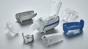
A second example comes from the production of insulin pens. According to Schubert, burrs that form as tool wear begins did not cause functional problems until the assembly stage. “Burr inspection was initially performed manually using a microscope and a micrograph: it was operator-dependent, resulted in false rejects, and provided no insight into trends, since only a ‘pass/fail’ result was available without any measured values,” said Schuberts. With in-process CT, burrs are now measured and objectively evaluated within a few seconds. Tool wear becomes visible in the trend before assembly errors occur. This reduces scrap and prevents customer complaints.
Digital Twin for the Product Lifecycle
The complete set of measurement data pays off over the entire product life cycle. Physical reference samples made of plastic change due to moisture absorption or UV exposure and require storage space under defined conditions. The CT data set does not degrade over time and can be archived as a digital twin of the sampled workpiece. In the event of a complaint, it can also be analyzed retrospectively in areas that were not measured during sampling. According to Schubert, during revalidation—for example, after a tool or machine change—a quick “as-is” comparison against the sampled twin is sufficient, focusing on areas outside the tolerance limits.
Conclusion
Device sales figures illustrate just how much the focus has already shifted: While CTs accounted for a single-digit percentage of Werth’s sales 15 years ago, the company reports that the figure is now over 50%. According to Schubert, some users are already operating second- through fourth-generation equipment and have built up a lead through well-established processes, program libraries, and digital twins—a lead that will be nearly impossible to catch up to in the short term. In the highly competitive field of plastic injection molding for medical technology, in-process CT measurement technology is thus likely to evolve from a differentiating factor to a prerequisite in the coming years.
Info Box: Relevant Standards and Regulations
MDR (EU 2017/745): Requirements for validation, documentation, and traceability of medical devices in Europe.
21 CFR Part 820 (QMSR): U.S. FDA quality requirements; as of February 2026, with a direct reference to ISO 13485:2016.
ISO 13485: Quality management systems for medical devices.
ISO 10360: Acceptance and verification testing for coordinate measuring machines; Part 11 covers systems using X-ray computed tomography.
VDI/VDE 2617 Sheet 13: Guide to the Application of ISO 10360 to Coordinate Measuring Machines with CT Sensors.
ISO 14253-1: Decision Rules for Demonstrating Conformity, Taking Measurement Uncertainty into Account